|
From Concept to
Contract
Not known to many, the “Super Pumper”
concept dates back to 1910 when Mr. William Francis Gibbs an
internationally renowned naval architect came up with an idea for
the “land fireboat”, but his ideas where not received with serious
consideration. In the 1930’s Gibbs had plans drawn up for his “land
fireboat” using two Zeppelin engines, but this was still just a
concept, while he was designing the fireboat FIREFIGHTER for New
York City. He could not get the land fireboat out of his head;
penning down designs and also showing practical reasons for his
idea: which included the land fireboat acting as a portable pumping
station delivering water from lakes ponds and other inland mass
water sources. Giving greater water pressures than existing fire
fighting equipment at the time, unfortunately for Gibbs such a
vehicle was still no more than just a dream. Not being possible, due
to engineering limitations that would restrict such a vehicle until
the 1960’s. Diesel engines that could fulfill this type of pumping
requirement and be light enough to mount on a truck did not exist,
as well as hose that could cope with the pressures in Gibbs’ design.
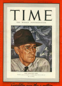
Mr. William Francis Gibbs went on to be come America’s foremost ship
designer going on to design 74% of the U.S. Navy’s fleet used during
World War II plus the passenger liner S.S. UNITED STATES. Gibbs
never gave up on his land fireboat, he became encouraged by newly
developed lightweight diesel engines for the British navy as well as
the U.S. Navy’s development of high pressure hoses that could
withstand the requirement of the envisaged fire fighting apparatus.
During 1962, Gibbs invited Mack Trucks to take part in the design of
what is known today as the SUPER PUMPER and its companion Tender;
with studies by Gibbs and Mack engineers into engineering
feasibility, design right through to construction and materials. The
DeLaval Turbine Inc was commissioned to design a multi-stage
centrifugal pump with a Naper-Deltic T18-37C diesel to power the
pumps; Gibbs and Cox Inc would provide the necessary services to act
as design agents leaving Mack Trucks acting as the general
contractor. Teams of managers, scientists and engineers from both
corporations were assembled to work on this project.
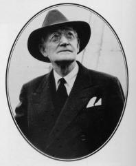
William Gibbs |
 |
20th April 1963 F.D.N.Y. experienced its busiest day to date, the
combination of several dry spells plus prolonged water shortages led
to one of the biggest fires on Staten Island. Staten Island was
mainly thick brush, oak and pine trees with a small clusters of
homes. On that day a series of small brush fires quickly committed
all Staten Island’s fire companies; there was almost no water
available due to the drought and poor water mains, additional fire
companies were dispatched from Brooklyn and Manhattan. Their
response time was hampered by the need for the additional companies
to be shipped across to Staten Island by ferry boats. As a result of
the delay in providing adequate fire cover, the total loss on the
Island exceeded
$2 Million with over 1300 firefighter and over 80 Fire companies
being committed, firefighter could do little to save property and
land due to the lack of water. Firefighters in the rest of the city
were kept busy in that twenty four hour period with over 2000 alarms
being transmitted for fires.
Gibbs watched the events of that day; after he analyzed all the
statistics he came to the conclusion that his land fireboat could
have had great effect on the outcome of the Staten Island fire. It
could have pumped water from the Tottenville water front providing
an unlimited supply of water to the working companies. This was it;
the time had come for his idea to become a necessity in a modern day
fire service. He approached the F.D.N.Y. The department’s officials
were enthusiastic about the idea of a large high pressure pumping
appliance. But one problem! The department’s funding for the next
financial year had been budgeted; this was a set back for Gibbs, but
he was determined to sell this idea to the City. After attending
several hearings and testifying to justify the expense, the approval
was eventually given and at 10:00am December 3rd 1963 Fire
Commissioner Edward Thompson signed the contract for Mack Trucks to
build the Super Pumper and it’s Tender at a cost of $875,000.00 to
the city. Commissioner Edward stated, “This will be the most
powerful firefighting equipment the world has ever known.”
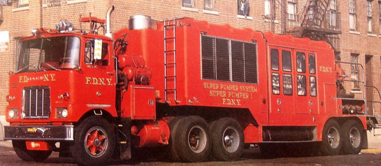
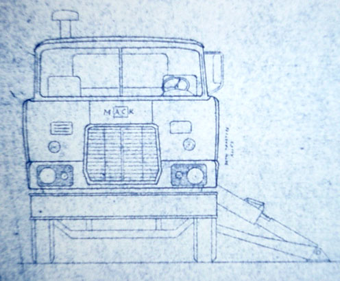
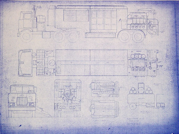
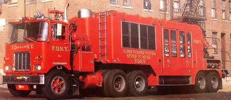
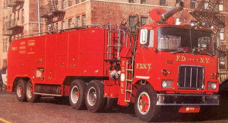
The Super
Pumper
The tractor utilized for
the Super Pumper was a commercial Mack, model designated F715FSTP.
The engine was a four stroke cycle Mack END864 V8 diesel of 255 HP.
An Allison CLT4460 six speed semi-automatic transmission was coupled
to the engine an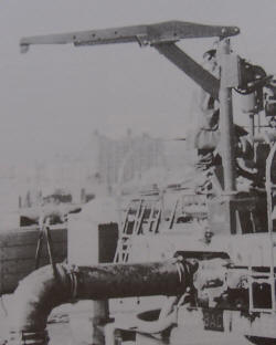 d equipped for a power take off unit to drive the
priming pump and starting air compressor for the pump engine.
Additional power take off units powered the air brake compressor
including the power steering pump. The semi-trailer was mounted to
the fifth wheel of the tractor. Mounted at the rear of the tractor
trailer is a DeLaval six stage pump having a built in piston type
valve to allow for operation in either pressure or volume positions.
To supply water to the pump there are four unchecked inlets to the
rear. Two of these are 4 1/2 inch while the other two are 12 inch
with 4 1/2 inch inlets set into their caps. There are also two 4 1/2
inch checked inlets on each side of the apparatus at the rear. There
are a total of eight 4 1/2 inch discharge outlets with four located
on each side of the apparatus. Directly coupled to the pump is the
Napier-Deltic engine this is an 18 cylinder turbo-blown compression
ignition, water cooled opposed piston type operating on a two stroke
cycle. The exhaust silencer is intended to reduce the overall engine
noise level within 6ft distance from the apparatus. On each side of
this silencer are 200 gallon diesel fuel tanks which can feed the
diesel independently or simultaneously. The pump engine is started
by air pressure (450PSI) provided from air tanks located on the
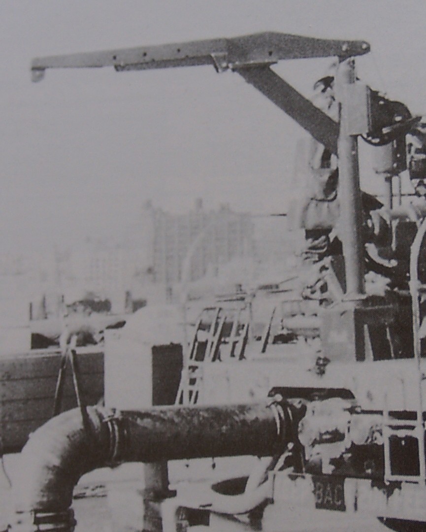
tractor. There is a single master shut off to prevent engine over
speeding. A mechanical crane is located at the rear to assist in
positioning and supporting the rigid 12 inch suction connections. By
the end of 1964, the pumping unit of the Super Pumper was
approximately 90% complete. d equipped for a power take off unit to drive the
priming pump and starting air compressor for the pump engine.
Additional power take off units powered the air brake compressor
including the power steering pump. The semi-trailer was mounted to
the fifth wheel of the tractor. Mounted at the rear of the tractor
trailer is a DeLaval six stage pump having a built in piston type
valve to allow for operation in either pressure or volume positions.
To supply water to the pump there are four unchecked inlets to the
rear. Two of these are 4 1/2 inch while the other two are 12 inch
with 4 1/2 inch inlets set into their caps. There are also two 4 1/2
inch checked inlets on each side of the apparatus at the rear. There
are a total of eight 4 1/2 inch discharge outlets with four located
on each side of the apparatus. Directly coupled to the pump is the
Napier-Deltic engine this is an 18 cylinder turbo-blown compression
ignition, water cooled opposed piston type operating on a two stroke
cycle. The exhaust silencer is intended to reduce the overall engine
noise level within 6ft distance from the apparatus. On each side of
this silencer are 200 gallon diesel fuel tanks which can feed the
diesel independently or simultaneously. The pump engine is started
by air pressure (450PSI) provided from air tanks located on the
tractor. There is a single master shut off to prevent engine over
speeding. A mechanical crane is located at the rear to assist in
positioning and supporting the rigid 12 inch suction connections. By
the end of 1964, the pumping unit of the Super Pumper was
approximately 90% complete.
| Length |
43'3" |
 |
| Width |
8' |
| Height |
11' 4" |
|
Weight |
68,500
pounds |
|
Maximum speed |
42 MPH |
|
Rated horsepower of pump engine |
2400 |
|
Fuel
carrying capacity |
400
gallons |
|
Pump |
6 stage 2 position |
|
Pump capacity |
8800 GPM at 350 PSI |
|
Serial number |
F715FSP1000 |
The Tender
The primary tender would be a flat hose
bed trailer instead of the hose reels indented in the original
design; unfortunately the intended design was not practical at the
time of manufacturing due to limited technology. When a working
model of the tender with reels was made, problems surfaced with the
hose butts on the reels that proved the design to be impractical. A
manifold system with gauged discharge outlets would also be included
in the trailers design. Utilizing the same basic Mack cab over
tractor as that of the Super Pumper, modifications were made to fit
an operating platform that would support the high pressure monitor,
designated model F715FSTT... When originally delivered, the Tender
had a large McEntyre monitor similar to those on the fireboats. This
was replaced with a large Stang "Intelligiant" monitor which had an
8 inch barrel operated by hand wheels including interchangeable tips
of 3, 3 1/2, 4, 5 inch and a 2000 GPM fog tip. The monitor was
supplied via the four 4 1/2 inch checked inlets with two located on
each side of the tractor. There were also hydraulically operated
outriggers on each side of the tractor located below the operating
platform attached to the frame. Their purpose is to stabilize the
rig and counteract the nozzle reaction of back pressure. These
outriggers were also equipped with mechanical interlocking devices
in the event of hydraulic failure. The maximum reach of a stream
thrown by the tender's monitor was 600 feet. The bulk of the trailer
consists of a divided hose bed with each compartment capable of
carrying 1000 feet of 4 1/2 inch hose. The front end of the trailer
was equipped with a large “walk in” type compartment. The rear axles
were steerable from a reverse seated position located at the rear
center of the trailer; this was to be removed in a later
modification. This apparatus was designed and manufactured so that
the tractor could easily uncouple from the trailer. This allowed for
the tractor, carrying the large monitor, to maneuver easily and into
tighter spots than wouldn’t be possible as a tractor trailer
combination.
| Length |
41'6" |
 |
| Width |
8' |
| Height |
11' 4" |
|
Weight |
60,000 pounds |
|
Monitor capacity |
10,000 GPM |
|
Reaction force of monitor |
5000 PSI |
|
Maximum reach of stream |
600' |
|
Serial number |
F715FSTT1001 |
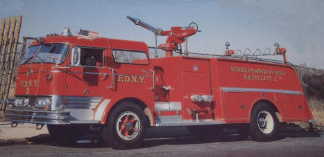
Satellites
The
Super Pumper System was developed out of necessity due to the
inability to build the tender as originally designed. The new
system consisted of the Super Pumper, Tender, and three
satellite tenders that were developed to carry the same amount
of hose and equipment as originally intended for the tender.
Each of the three satellite
were
built on the Mack "C" model cab designated model C85FD.
They were equipped with Mack END673 176 HP diesel engines and
manual transmissions. Each was capable of carrying 2000 feet of
4 1/2 inch hose and had a Stang "Intelligiant" monitor that had
a 6 inch barrel which was manually controlled. These monitors
had a water delivery capability of 4000 GPM and had 2, 2 1/2, 3,
3 1/2, and 4 inch tips as well as 700 and 2000 GPM fog tips.
Each satellite had four inlets with two on each side. There was
one checked and one unchecked inlet on each side. When lines
were supplied to a satellite they were hooked up to the
unchecked inlets first.
All three
satellites were equipped with portable manifolds. These
manifolds had 4 1/2 inch inlets and either six 2 1/2 inch gated
outlets or two 3 inch and four 2 1/2 inch gated outlets.
Weighing a little over 200 pounds, the portable manifolds were
utilized efficiently at operations requiring many hand lines the
Super Pumper could supply the manifold from a remote location
with the manifold positioned in front of the fire scene.
SATELLITES
| Length |
25'7" |
 |
| Width |
8' |
| Height |
10'9" |
|
Monitor
capacity |
4000 GPM
Butts |
|
Model designation |
C85FD |
|
RUNS AND WORKERS |
|
SUPER PUMPER
and
TENDER
The last response made
by the Super Pumper occurred on
April, 24th, 1982. |
YEAR |
RUNS |
WORKERS |
|
1965 |
46 |
7 |
|
1966 |
163 |
59 |
|
1967 |
114 |
41 |
|
1968 |
237 |
67 |
|
1969 |
219 |
56 |
|
1970 |
234 |
78 |
|
1971 |
206 |
66 |
|
1972 |
165 |
54 |
|
1973 |
190 |
81 |
|
1974 |
231 |
114 |
|
1975 |
216 |
134 |
|
1976 |
99 |
63 |
|
1977 |
41 |
28 |
|
1978 |
24 |
17 |
|
1979 |
38 |
26 |
|
1980 |
25 |
12 |
|
1981 |
26 |
11 |
|
1982 |
11 |
4 |
|
TOTAL |
2285 |
918 |
The above text is an adaptation of
John A. Calderone’s book entitled, The F.D.N.Y. Super Pumper
System. If you are looking for a more in-depth history of the
above F.D.N.Y. vehicles mentioned in this article, I strongly
recommend you purchasing a copy of the book which includes over
100 photos and illustrations. The book is still available from
the following sites:
http://www.fireapparatusjournal.com/sp-order.pdf and
www.westchestercollect.com. Also available are copies of the
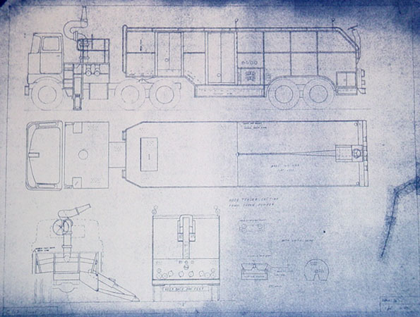
blue prints for the Super Pumper System from
http://www.grovegraphics.com/blueprints.htm
The blue-line blueprint will be made
from the original velum drawing by a California firefighter that
is over twenty-five years old. This print is NOT a photocopy but
an actual blueprint. The overall size of this blueprint is
approximately 20 1/2 x 15 1/2 inches.
Click Here for
Review
|