|
About the Author: Fred Keislair is a member of the Zoetermeer Fire Department is a paid and volunteer department. He works in the Bureau of Training and also act as a lieutenant with engine co. 841 of Oosterheem Fire Station. We also cross staff the County Hazmat Unit and Water Rescue RIV. Part 1 | Part 2 | Part 3 | Part 4 | Part 5 This article is about my next
radio-controlled model. I recently finished (although I now know
that a working radio-controlled model is never really finished,
there is always something to improve or maintenance to do) and have
started on my next new model. Maybe it is hard for you to believe,
but the Sweet Lake City Fire-Rescue apparatus was a test model, to
learn how to make a radio-controlled model.
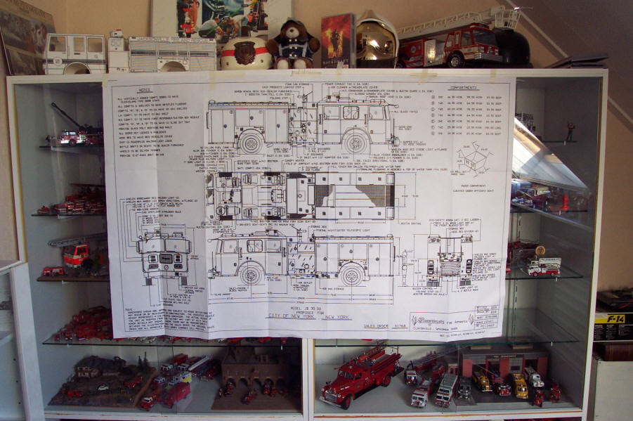
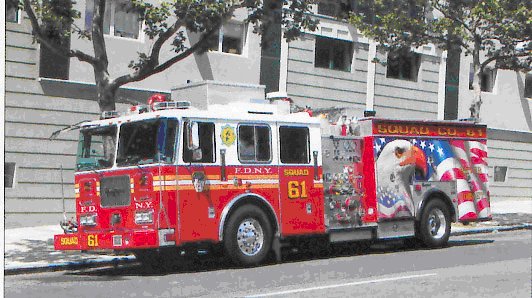
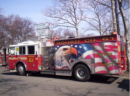
For those of you who couldn’t recognize the company patch, I will give the answer. The model I will be making is the Seagrave Rescue pumper with the new Commander II cab, the apparatus of FDNY Squad company 61 with the “9/11 never forget” mural on it.
I was a FDNY buff long before
the attack on the WTC on 9/11 and had already made several FDNY
models, but in a smaller scale. As mentioned before, the SLFD rescue
pumper was only a test, and if you have read the feature about that
model you know that I had started way back with building a Mack CF
Aerialscope. So why did I decide to make that Squad unit, and
not another FDNY pumper. Well it was hard to get the drawings of
that model, and my first investment was buying the Code 3 diamond
plate model in 1:32, because then I would have a terrific model to
duplicate and I would simply have to double all the measurements to
get it in approx. 1:16 scale. The 9/11 mural and all the graphics
would make it stand out at any exhibition and last but not least, 61
is a special number for me, since I’m born in 1961. Does one need
more reasons to make this squad unit.
Making the monitor completely
remote controlled will be a challenge, but I will get it done.
A first test showed that the pump at full speed would empty the
water tank (cap. 0.7 liter) within 1.5 min, with a nice solid water
stream and a good reach of the water jet, which should knock down
any “model house” fire within seconds !!
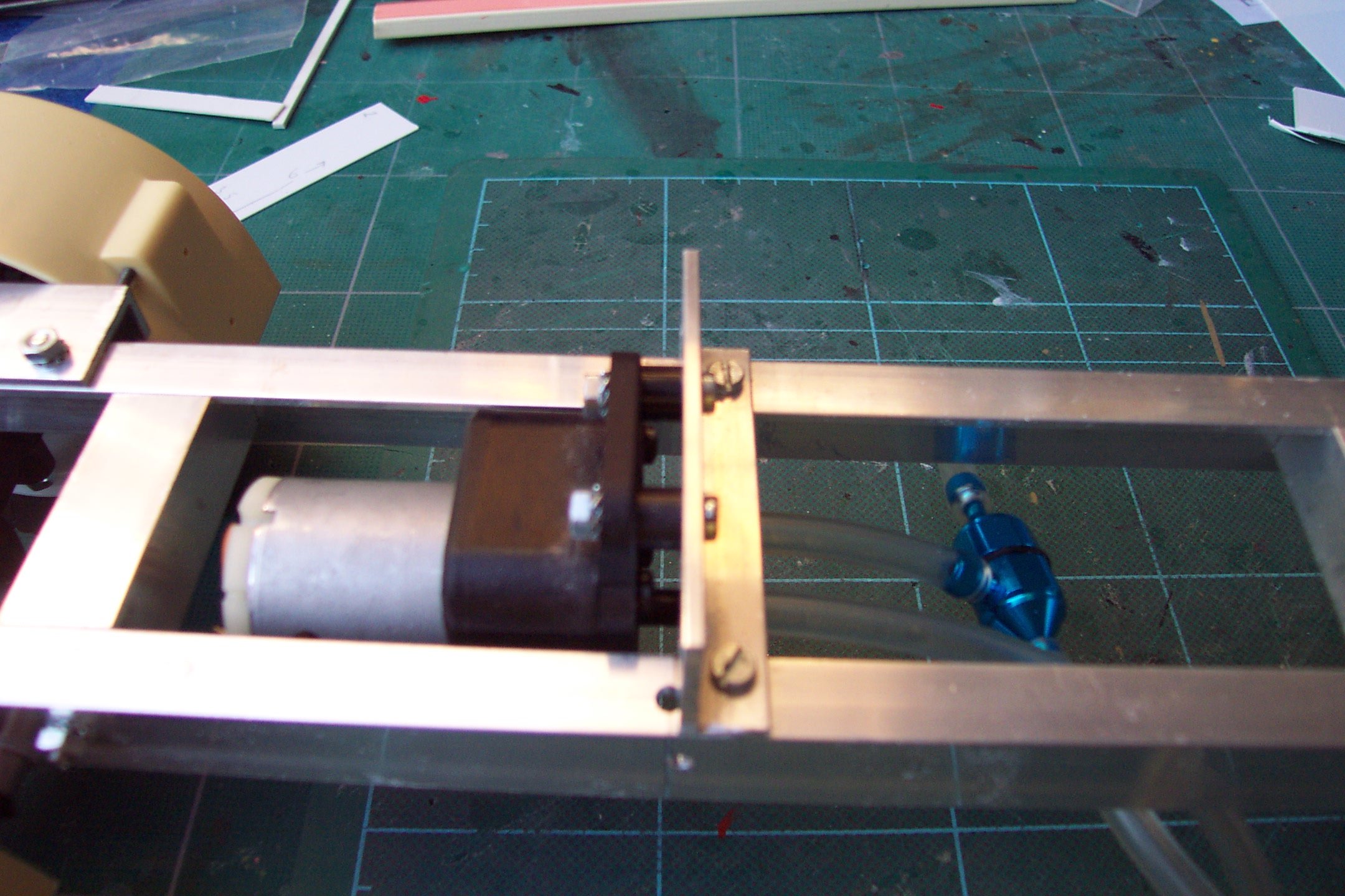
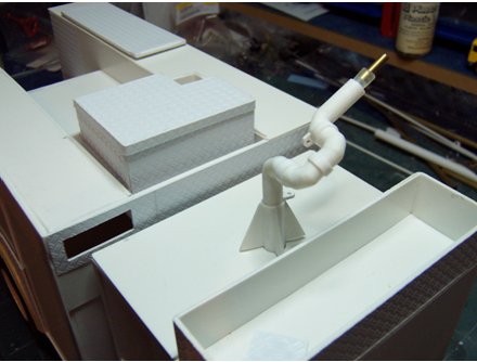
Picture 1: Close-up of the pump and hose
connections from the bottom of the tank. Since the tank is placed
over the chassis I had the make two connections to the bottom of the
tank to draft the water out.
Part 3
Since the last episode the building
of the body has come to a stop. But work has proceeded on the
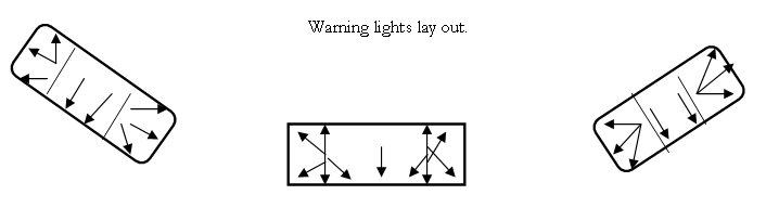
warning lights. The original Squad 61 was delivered with the FDNY
style red and clear warning lights with rotators. But this was later
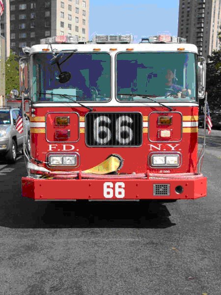
changed to the new LED warning lights. I choose to make this
version, the LED lights on the corners, and a red/white rotator in
the middle. But I wasn’t sure what the color of the lights were, so
I got help from Ken, who sent me a picture with similar warning
lights on an other FDNY rig.
|
 |
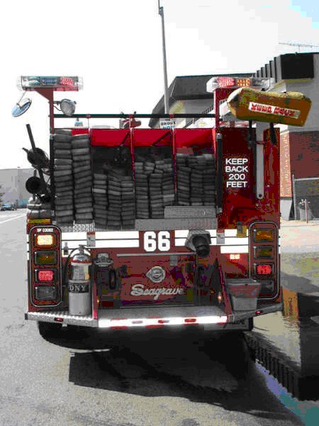 |
I had already made one prototype, with a white and a red part, looked real nice, but now I discovered that the front LED warning lights are divided into three all red parts, and the rear lights into three parts with yellow in the middle. I made a new type with three red Led’s in the outer parts and two in the middle. The rotator light in the middle of the roof will be the same as the light on my SLFD 39 apparatus. Each rotator will be made using five LED’s placed in a circle, the sixth will be a single red one placed in the middle of the two rotators flashing when the white light passes. All the warning lights will have a clear cover.
Concerning the rear body I want to make it out
of two parts; one part will be the body that will be completely red,
all the other parts that will have a different color, like the wheel
fenders and all the treadplate parts will be detachable, so I can
have the body spray painted with out using masking tape. This works
as follows, the parts that are treadplate are thinner then the other
parts. ( Body is made out of 2 mm plastic sheets, the outline for
the doors is an extra 1 mm strip.) I use a 0.75 mm plastic sheet for
the detachable parts, make it fit to the place were the tread plate
comes. Then I drill 2 mm holes in it, stick 2 mm plastic tubes in
the holes and glue the pins to the 0.75 mm plate. When the glue is
dry, I take the sheet with the pins off, sand off the out sticking
extra material of the pins and glue the Plastruc Diamond Treadplate
to the plastic sheet. No I have a tread plate part that will fit
exactly with the pins into the holes of the body.
Like mentioned before you have to plan ahead, so you don’t get
surprised by any problems. I plan to make the master switch, for the
receiver and battery in the big box on top of the hose bed.
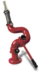
I have also been working on the Akron Nozzle on the pump body, but I
wasn’t satisfied with the curves a fellow builder made in copper
tubes. The monitor was way to big, so I will have to make it using
plastic tubes.
I have been figuring out several methods making the monitor fully
functional. I think it will end this way;
Next episode will have some new pictures of the
model and the finished warning lights.
I have become a member of a scale model builder group with 1:16 and
1:14 radio controlled scale model trucks, and they have a complete
lay-out for exhibitions. We decided that my fire engines definitely
need a proper Fire House. After a meeting where we discussed several
new items, like a new bridge, a truck stop garage and a bus station,
I proposed two different fire houses to be made. We all agreed that
this is the fire house that will be build to house the model fire
trucks on exhibitions.
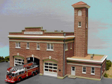
Photo provided by Pine Canyon Models
Work has started on this station during the
evening hours when I’m on watch. The fire house will have remote
controlled opening doors, an alert tone, dispatch message and the
lights will switch on in the building. This will be a nice project
during the winter evenings, when there are no emergencies.
“The making of : Squad 61”
Part 4
First I have to fill you in on the photo’s
that are in this article. I mentioned before that I want to make all
the diamond tread plate parts separate from the body work. Here are
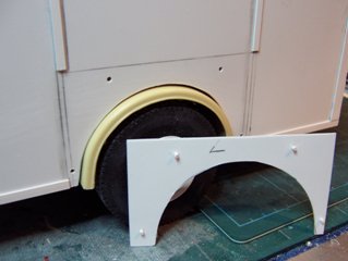
some examples how I did that. Picture 1 is the rear wheel cover
plate.
 |
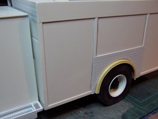 |
As you can see the plate has pins just like a
model kit. The “L” means that I know that it is the Left side plate,
and on the second picture you can see that it fits perfectly to the
body. The body all ready has the outlines for the doors. But since I
have to find away to make the door handles, or slam locks, I haven’t
made them yet. But you can imagine that it is real easy to make a
nice clean door, since I just have to measure the doors, cut them
out of a 1 mm. plate, and I have good sharp lines and door openings.
I have made one mistake on the left side, as I found out later.
Underneath the first left side compartment is the Airbag Storage,
and that means that the door isn’t the same as the right side. There
is an extra tread plate covered storage compartment. This problem
can be changed easily, so that will be solved one of these days.
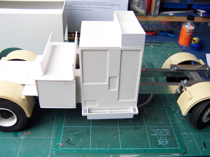
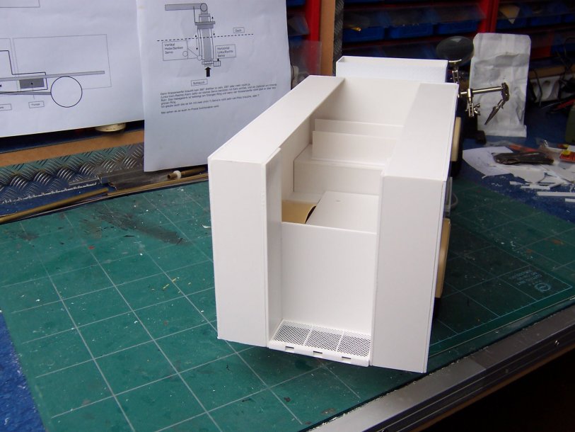
The rear of the hose bed has been worked on also. At his picture you can see that I made the hose bed.
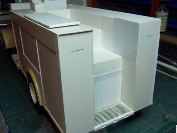
In stead making it a straight flat hose bed, I
altered it a bit. The hoses on the model are going to be just one or
two layers, not a complete hose load and I need the storage space
underneath to house the batteries, and electronics. So that is why I
changed it. The rear step and the roll-up and compartment door above
it are also made using the take-apart-principle. It can be taken off
for painting and will be fixed after the whole body is spray
painted.
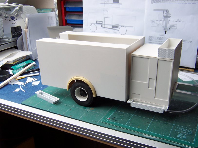
On top of the body one of the roof compartments is visible. I have
finished only one, since I ran almost out of Plastruc Diamond tread
plate. My local hobby shop has them on order for me, so I made other
parts that didn’t need big pieces of this material like the front
bumper.
Also visible is the tread plate to the side of the body. I noticed
that on a picture I received of the real rig. I think that is one of
the many changes that are made to a fire engine that is frequently
used and are caused by adjustments requested by the crew who work
every day with the apparatus.
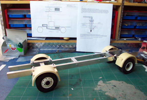
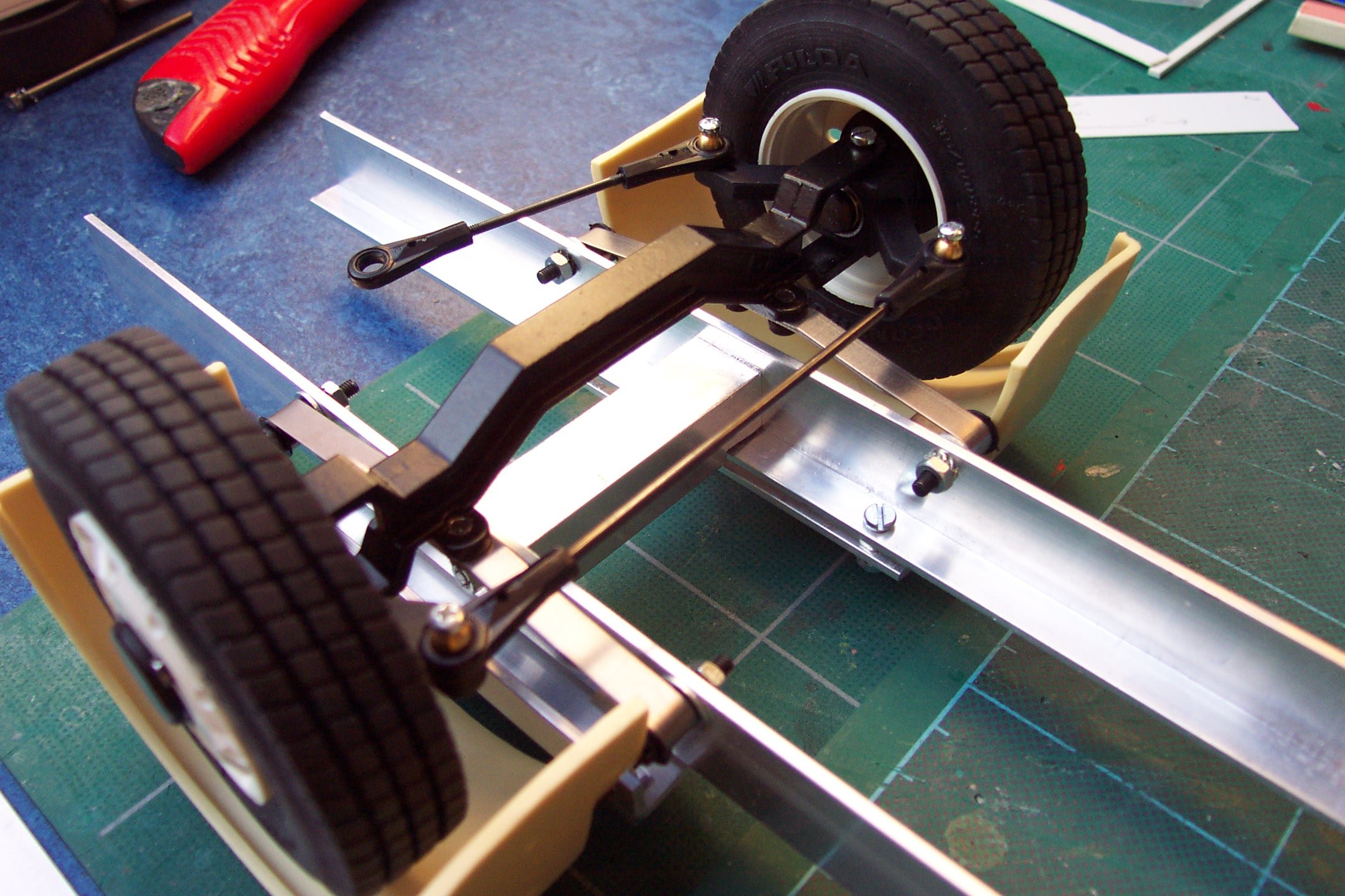
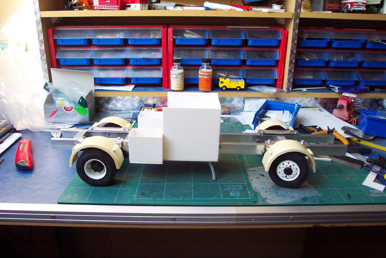
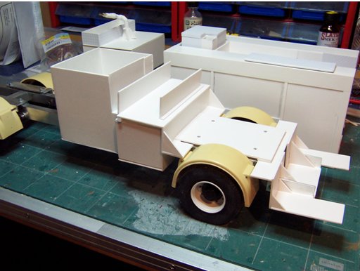
Underneath the body is the water tank and the storage room for the batteries and electronics. This picture shows you that I made a base plate over the chassis to house all the electronics. It is also used to get the body into place and to make the whole unit a solid truck. Since it will be Radio Controlled and it will drive around exhibitions a lot you don’t want your model to fall apart after every run. So al the modules have to be secured by screws, or even Lego blocks to be kept in place (that is a trick a learned from a German friend who also has beautiful RC fire trucks).
The next picture shows the Akron monitor, that will become fully functional. The nozzle tip isn’t ready yet, that has to be made and for now I just put a small cupper tube in the hose. Inside the curved plastic tube is a flexible hose that allows the monitor to move vertically and by this I don’t have to worry about leaking water (Keep It Simple S…. principle) If I don’t succeed in making it move up and down while rotating the monitor will be fixed in a raised position and will only rotate approx. 270°. This option will eliminate a lot of the fun knocking down a model house fire, but if my solution that I figured out isn’t 100% failure proof I will have to choose for this option. Nothing is so annoying as something that won’t work when you are presenting your model to the audience.
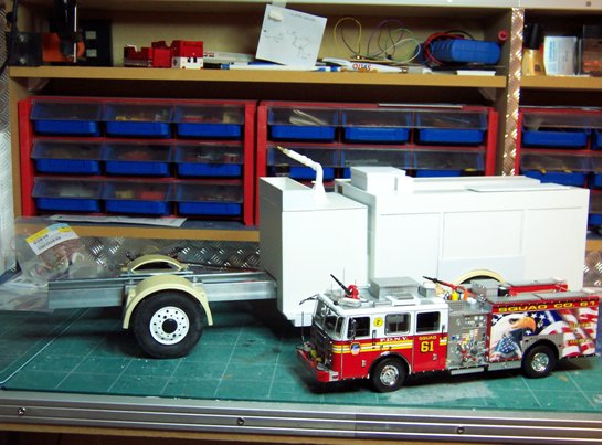
A parting shot, as they like to say in FAJ, the Code 3 Diamond Plate 1:32 scale model in front of my Platinum Plate Model to be… in scale 1: 14,5
Just to show you how the dimensions of this model are going to be.
Since the front bumper has been made after I
took these pictures, the next step will be making the cab. That will
be a turning point because then the model will start to look like
the real rig.
The making of : Squad 61” Part 5
After a long period of radio silence is here is a new episode of the
making of Squad 61. As you all may have noticed I have been
extremely occupied by making a Fire House to show at scale model
truck exhibitions. This station is now ready to use, although I
still want the doors to be motorized so I can open and close them.
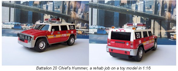
An other project that I have finished is a FDNY battalion Chief
Buggy. This is a 1:16 scale Hummer, and I know that the FDNY doesn’t
use those vehicles, but it was the closest I could get to look like
a Ford Explorer or Chevrolet Suburban. This model is fully Radio
Controlled, with a master switch for the receiver that also
activates the head and tail lights. The light bar is a Fred’s custom
model, with two revolving lights. This time I left the lower part of
the clear cover unpainted so the white LED’s give a red and white
light. The siren is a 20 sec. electronic recording print with 16
sec’s of Wail and 4 sec of Yelp and then start’s all over again.
At the rear two additional yellow flashers were installed on the
roof and in the front two red flashers between the head lights. When
parts of the Squad 61 model will be chromed the Bullbar and side
steps of this model will also be chromed.
Battalion 20 Chief’s Hummer, a rehab job on a toy model in 1:16
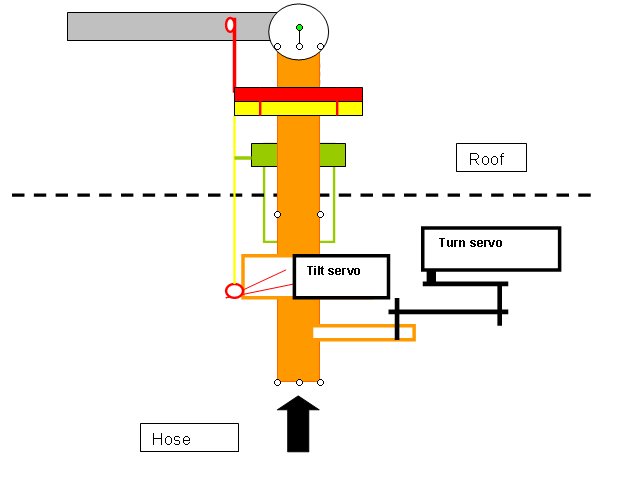
Work on the Squad had come to a stop due to problems making the Akron Monitor functional. I wanted the monitor to move horizontal and vertical in every position and that caused some problems. It is easy to lift the nozzle up using a servo, and its is easy to rotate the nozzle, but making these two functions work at the same time is something different. And to add another challenge to it I wanted the monitor to look like the original as much as possible.
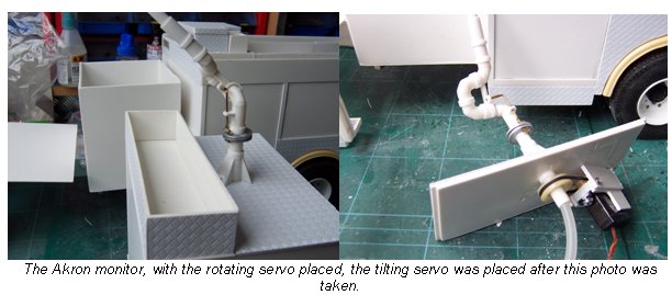
The Akron monitor, with the rotating servo placed, the tilting servo
was placed after this photo was taken.
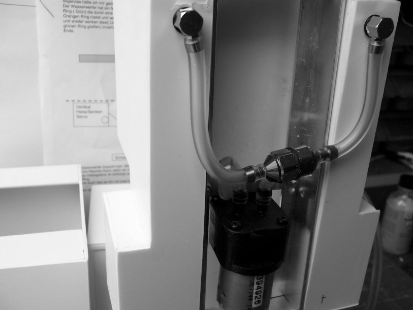
In these pictures you can see how I have solved this problem. The
first servo is to rotate the monitor using a rubber band and some
cassette deck wheels. The advantage of the rubber band is that if
the monitor is blocked it won’t cause any damage to the servomotor.
The tilting of the monitor is done by a small servo that moves a
metal ring up and down along the vertical shaft, and above that ring
is a second ring that is attached to the movable section of the
monitor. Inside the monitor is a flexible hose towards the end of
the nozzle, making it water tight.
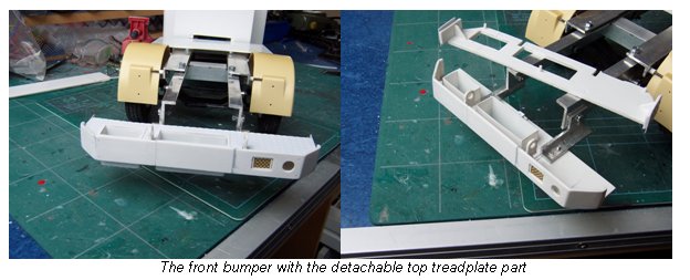
An other job that was done was the front bumper. This was a short
job for a weekend, and when I had it finished, using the original
drawings for measurements I discovered that it was 5 mm to wide
compared to the front wheel fenders. That would look really weird,
so I cut it into two, took out the 5mm and glued it back together.
The bolts on the front bumper are metal pins that you can find in
the collar of a new shirt when you open up the package.
The tread plate is not fixed, since I will have to install the side
mounted warning lights and paint the bumper and tread plate in
different colours.
During the Intermodellbau Exhibition in
Germany, (when you can drive two and a half hours to visit an
exhibition and stay in the USA, when I drive that distance I’m in an
other country !) I found what I had searched for. Bolts for the
front and rear wheels. These tiny bolts are chromed and make the
wheels look more like the original ones.
I also invested money in a master electronic circuit, so I can
connect all lights in the front and in the rear to two small prints
that are connected to the master print by small flat-cables. This
will make the electronics more fail safe and will look more
professional. This master print also has breaking lights function,
with an automatic switch off after 6 sec’s, and a directional lights
function that will also switch off automatically after a few seconds
after you have made the turn.
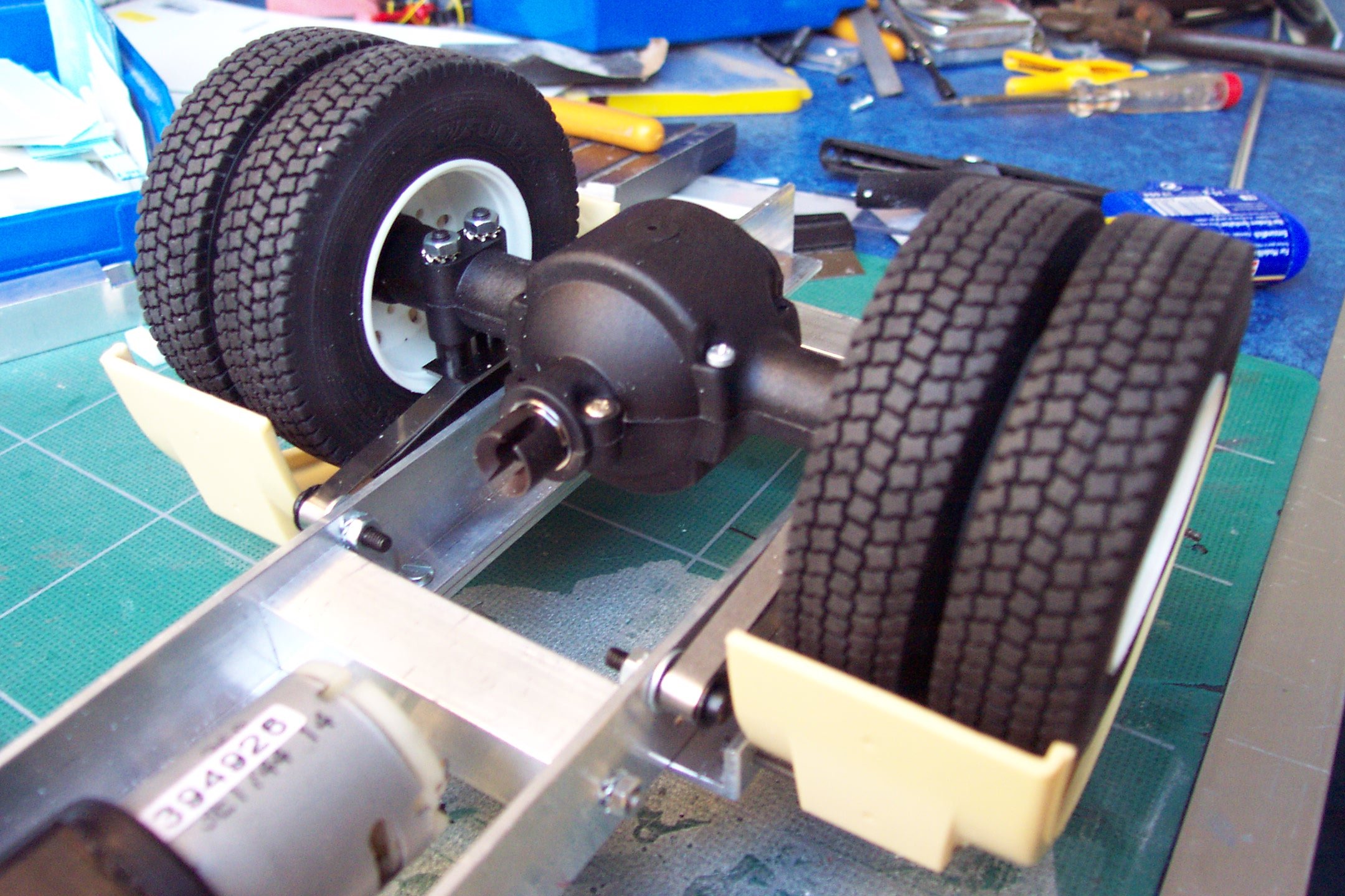
Next on the program is finishing all the big work on the compartment
body, closing the water tank, and installing the electric motor on
the chassis with drive shaft. When that is in place I can start on
the inside of the crew cab and the cabin itself.
Bad news it that I wanted to have the model finished around
September this year. But I have to be realistic, that is impossible,
but I hope to have to crew cabin and compartment ready by that time,
so it will starts looking like the real one.
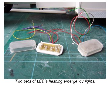
I also spend time on making the lightbars. The LED bars on the outer
corners are ready, and tested, the center one with the three
rotators is still a challenge, allthough I have figured out a way to
get it done.
More bad news came after an other Exhibition.
There I found out while talking to a fellow scale modelbuilder that
I had mounted the rear wheels the wrong way. Adjusting this would
make the wheels stand wider apart, making it necessary to take of
the rear fenders and making them wider, and the front fenders, and
….. take apart the rear body. This also implied that the front
bumper, that was to wide at first and that I had narrowed, was right
from the beginning! So I had to make a new front bumper also. The
good news is that now the measurements of the model are almost
exactly in scale, so that I don’t have to adjust the width of the
model any longer but I can use the measures on the drawing.
Other good news is that while I had the rear body in pieces I made
some adjustments how to fix the body to the chassis. So it all turn
out good.
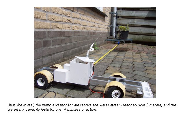
Just like in real, the pump and monitor are tested, the water stream
reaches over 2 meters, and the watertank capacity lasts for over 4
minutes of action.
Hope that you enjoy the photo’s and since work
on the model shifted in to a higher gear a new up-date will follow
soon.
Fred